Utility and resilient power
Confirm available utility capacity, A/B physical separation, transformer and switchgear topology, UPS or STS strategy, generation, BESS and rack-level metering.
AI DATA CENTER
DFT translates rack density, compute scale and deployment timing into coordinated building, power, cooling, network, monitoring and commissioning requirements.
Contact DFT ↗
DFT APPROACH
High-density AI projects cannot treat structure, power, cooling and network as separate decisions. DFT begins with the final GPU load and works backward to utility capacity, heat rejection, water flow, rack layout, fiber paths and service clearances.
Our responsibility can span design, build, supply coordination, supervision, testing and 24×7 operations, with each project role stated clearly.
EXECUTIVE OUTCOMES
DFT brings power, heat rejection, compute interfaces and operations into one capacity model so executive decisions can be tied to measurable readiness.
Confirm available utility capacity, A/B physical separation, transformer and switchgear topology, UPS or STS strategy, generation, BESS and rack-level metering.
Convert rack kW and liquid heat-removal ratio into chilled-water capacity, CDU interfaces, flow, differential pressure, water quality, leak detection and residual-air cooling.
Coordinate concentrated floor loading, rigging paths, maintenance clearances, MMR, diverse fiber, non-blocking spine–leaf and 400G/800G-ready pathways.
Close alarms, asset labels, test records, as-builts, O&M manuals, training and escalation workflows so the facility can be monitored and maintained immediately.
MARKET SHIFT
Room-level air cooling · general enterprise traffic · distributed alarms
Direct liquid cooling · high-volume east–west fabric · token, watt and SLA visibility
ENGINEERING DEPTH
Capacity, redundancy, interfaces, measurement and maintainability are engineered as one cascade—not as disconnected equipment packages.
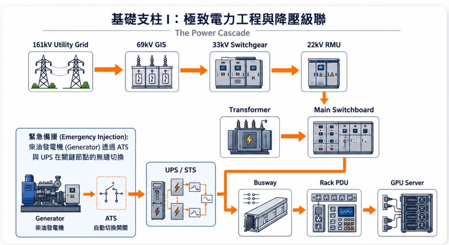
Utility, transformers, switchboards, UPS or STS, busway and rack PDUs share one load and protection model.
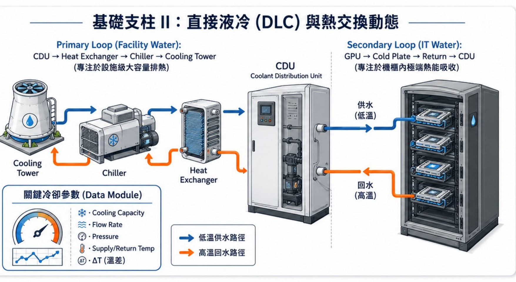
Facility water, CDU and IT water loops are separated, isolatable, measurable and maintainable.
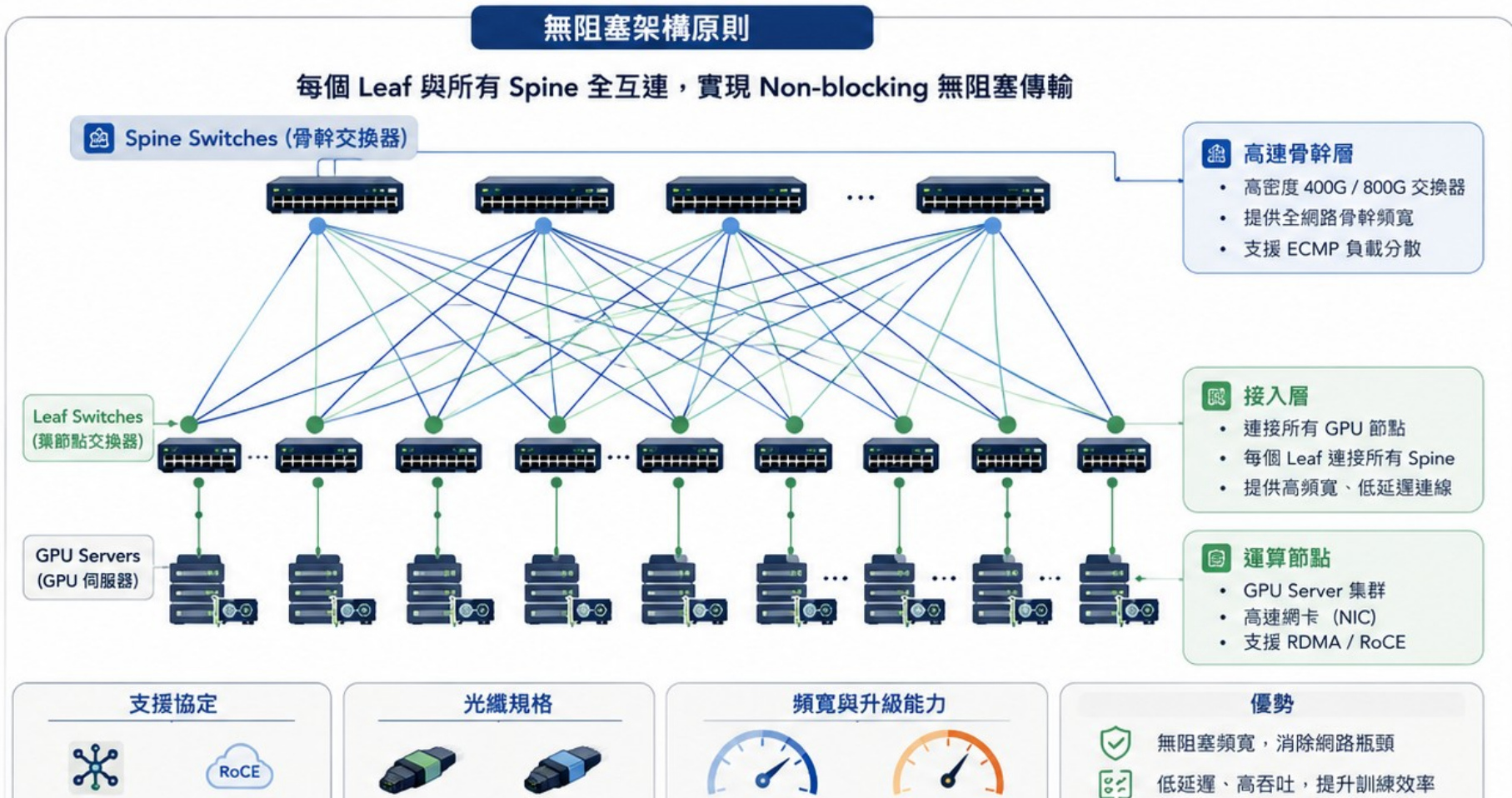
GPU east–west traffic, MMR, diverse carrier routes, DCI and cross-border circuits are coordinated early.
18 WORK PACKAGES
Seventeen foundation packages plus one optional fit-out package keep civil, MEP, cooling, fiber, controls, testing and handover under a clear interface structure.
ONE SOURCE OF TRUTH
Every assumption requires an owner, source, revision, tolerance and approval before it becomes a construction or purchasing commitment.
Capacity, redundancy, environmental limits and responsibility boundaries.
Utility intake, fault level, protection and A/B power paths.
Primary and secondary loops, flow, pressure, water quality and bypass.
Space, loading, access, service clearances and airflow.
Quantities, performance requirements, long-lead items and risk.
Test scripts, witness points, tolerances and signed evidence.
COMMISSIONING
DFT coordinates acceptance interfaces, failure scenarios, punch-list closure and operational handover so every result remains traceable to drawings, equipment, circuits and monitoring points.
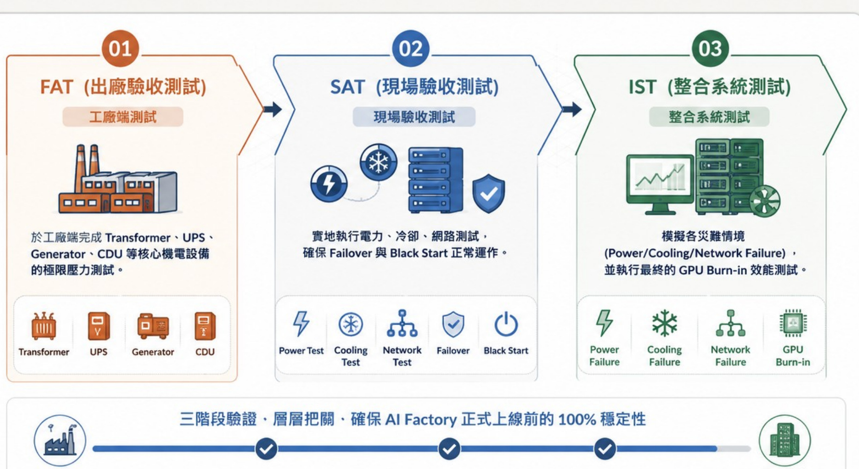
Review, witness and track vendor findings before shipment.
Verify equipment and electrical, cooling, controls and network interfaces.
Prove alarms, transfer, recovery and resilience under controlled faults.
Deliver scripts, trends, punch lists, as-builts, O&M manuals and operator training.
DELIVERY MODEL
Each stage has defined inputs, decision gates and evidence so schedule, cost and future expansion remain aligned.
Capacity, equipment, phasing, codes and existing-site constraints.
Structure, power, cooling, fiber, safety and logistics.
Drawings, calculations, materials, test criteria and package boundaries.
Inspection, concealed works, labeling, firestopping and change control.
Functional and integrated testing, closeout, as-builts and training.
CLEAR SCOPE BOUNDARY
SCOPE & DELIVERY
IT load, growth phases, floor loading, logistics, fire compartments and maintenance access.
Utility, transformers, switchgear, UPS, generators, busway, rack PDU and protection coordination.
Chillers, towers, pumps, CDU, manifolds, water quality, leak detection and residual air cooling.
Structured fiber, OOB, storage, DCI and validation of high-speed network interfaces.
FAT, SAT, IST, burn-in, failure scenarios, evidence packages and acceptance criteria.
DCIM, BMS, EMS, NOC, SOP/EOP, KPI, spares and expansion records.
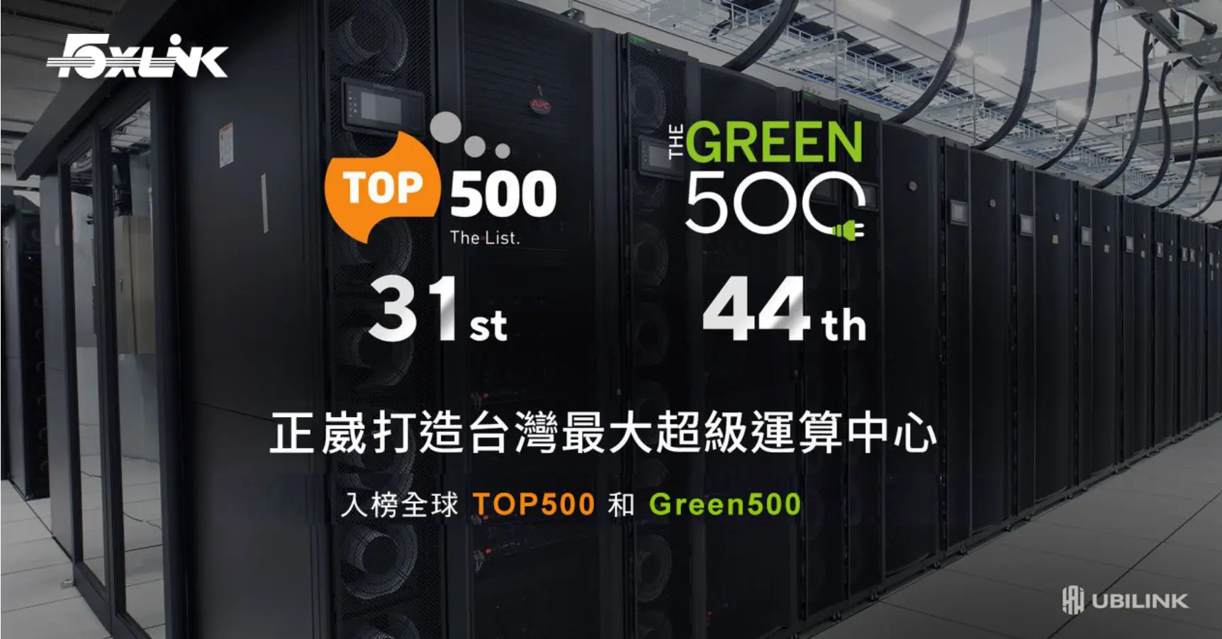
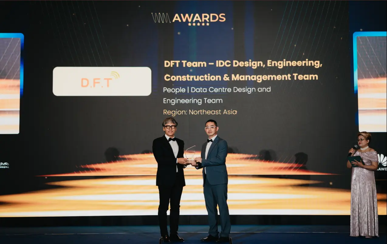
W.Media Northeast Asia Cloud & Datacenter Awards recognition for DFT's IDC design, engineering, construction and management team.

Figures are reported in DFT-supplied project material. TOP500 and Green500 are rankings of the computing system; PUE is the stated project operating metric. They are not third-party data-center tier certifications.
REAL FACILITIES
PROJECT INQUIRY
Provide GPU type, rack count, rack kW, site and target go-live date to begin a capacity review.